








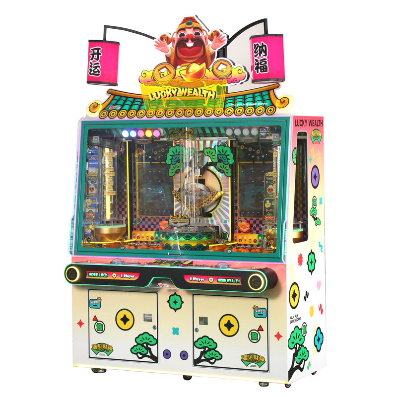
Most coin pusher faults can be traced to a small number of mechanical, coin-handling, sensor, or power-related problems. The safest repair process is to identify the symptom, isolate the affected subsystem, and replace only the confirmed faulty component rather than changing the motor, coin acceptor, or control board without diagnosis.
This guide is written for arcade operators, FEC maintenance teams, distributors, and trained in-house technicians working with commercial coin pusher machines. It covers common faults, safe operator checks, mechanical repairs, replacement-part compatibility, maintenance, and the point at which a machine should be referred to the manufacturer or a qualified service technician.
Important safety note: Disconnect the machine from its power source before opening the cabinet, removing guards, clearing internal jams, adjusting moving assemblies, or replacing parts. Live electrical testing, power-supply repair, control-board component repair, and work involving stored electrical energy should only be performed by a qualified technician.
Quick Coin Pusher Troubleshooting Chart
Start with the visible symptom instead of immediately replacing a component. The following chart summarizes the most common faults and the safest first checks.
| Fault Symptom | Likely Causes | Safe Initial Checks | Possible Parts or Support |
|---|---|---|---|
| Machine has no power | Disconnected supply, faulty outlet, power switch, fuse, loose connector, or failed power module | Unplug the machine, inspect the power cord, confirm the outlet works, and check visible fuses and connectors according to the service manual | Fuse, switch, power cable, or power-supply module |
| Pusher plate does not move | Obstruction, loose linkage, failed motor, worn gearbox, limit-switch fault, or control problem | Disconnect power, remove visible obstructions, and inspect the linkage, fasteners, and accessible switches | Motor, gearbox, linkage, bearing, or limit switch |
| Pusher moves slowly, unevenly, or with jerking | Dirty guides, worn bushings, damaged gears, misalignment, or an overloaded mechanism | Power down the machine, clear debris, and manually confirm that the pusher assembly can move smoothly without binding | Guide rail, bushing, bearing, coupling, motor, or gearbox |
| Coins repeatedly jam | Foreign objects, incorrect coin or token size, damaged coin guide, dirty coin path, or misaligned entry mechanism | Disconnect power, empty the coin path, remove debris, and inspect the guides for damage or incorrect alignment | Coin guide, chute, acceptor, or mounting bracket |
| Valid coins are rejected | Dirty coin acceptor, incorrect calibration, unstable supply, incorrect coin settings, or damaged sensor | Clean the accessible coin path and optical area according to the acceptor manual and confirm the configured coin or token type | Coin acceptor, sensor, wiring harness, or power module |
| Irregular ticket or reward output | Sensor obstruction, ticket dispenser issue, incorrect settings, loose wiring, or control-board fault | Check for visible obstructions, empty ticket paths, loose plugs, and error indicators without opening energized electrical assemblies | Sensor, ticket dispenser, wiring harness, or control board |
| Grinding or knocking noise | Gear damage, loose linkage, worn bearing, misalignment, or an object trapped in the mechanism | Stop the machine immediately, disconnect power, and inspect the mechanical drive before operating it again | Gearbox, coupling, bearing, linkage, or fasteners |
Understanding How a Coin Pusher Machine Works
Before attempting any repairs, it is essential to understand the basic operation of a commercial coin pusher machine. A typical machine consists of a coin entry and validation system, a moving pusher plate driven by a motor and gearbox assembly, a playfield containing coins or tokens, limit switches or position sensors, a power supply, a control board, and the supporting cabinet structure.
The pusher mechanism normally operates in a repeating forward-and-reverse cycle. The drive motor transfers motion through a gearbox, crank, linkage, belt, or coupling, depending on the machine design. The pusher plate advances to move coins toward the collection edge and then retracts to begin the next cycle.
Coin acceptors validate coins or tokens and route them into the playfield. Sensors may monitor coin entry, motor position, ticket output, payout mechanisms, doors, and other operating functions. Because these systems work together, a visible symptom may have more than one cause. For example, a stationary pusher may be caused by the motor, linkage, position sensor, control signal, or a mechanical obstruction.
Safety and Repair Responsibility Levels
Not every repair should be performed by ordinary venue staff. Dividing maintenance work into clear responsibility levels reduces the risk of electrical injury, mechanical damage, incorrect settings, and unnecessary part replacement.
Level 1: Operator Checks
Routine checks suitable for trained venue staff include:
- Disconnecting the machine and clearing visible coin-path obstructions
- Cleaning accessible coin guides, glass, playfield areas, and sensor covers
- Checking for loose external plugs and visibly disconnected low-voltage connectors
- Inspecting moving assemblies for obvious foreign objects
- Recording error messages, unusual sounds, and the conditions under which the fault occurs
- Restarting the machine according to the manufacturer’s documented procedure
Level 2: Trained In-House Technician
Repairs such as replacing modular motors, gearboxes, coin acceptors, sensors, switches, wiring harnesses, and power-supply modules should be handled by personnel who understand lockout procedures, component compatibility, electrical ratings, and the machine’s service documentation.
Level 3: Manufacturer or Qualified Service Technician
Contact the manufacturer or a qualified technician for control-board component repair, firmware-related faults, repeated fuse failures, damaged high-voltage assemblies, unidentified short circuits, structural cabinet damage, unsafe glass damage, or faults that remain after normal subsystem checks.
Diagnosing Power and Pusher Movement Problems
The Machine Has No Power
Begin with the external power source. Confirm that the outlet is functional and that the machine’s plug, power cable, main switch, and emergency-stop system are in their normal operating condition. Disconnect the machine before inspecting internal fuses, terminals, or connectors.
A blown fuse should not be replaced repeatedly without identifying the reason it failed. A stalled motor, damaged cable, shorted module, or incorrect replacement fuse can cause repeated failures and additional damage. Always use the fuse type and rating specified by the manufacturer.
If the external supply and accessible fuse are normal but the machine remains inactive, a trained technician should inspect the low-voltage power module, wiring harness, control-board indicators, and interlock switches using the machine’s wiring diagram.
The Pusher Plate Does Not Move
Disconnect the machine and inspect the playfield and pusher path for trapped coins, loose hardware, damaged prizes, or foreign objects. Check whether the pusher linkage has separated from the motor or crank assembly and whether accessible fasteners have become loose.
If the mechanism moves smoothly by hand after power has been disconnected, but does not operate during a normal cycle, the problem may involve the motor, gearbox, limit switch, position sensor, wiring, or control system. If the mechanism is difficult to move manually, inspect the guide rails, bushings, bearings, linkage, and plate alignment before replacing electrical components.
The Pusher Moves Slowly or Produces Unusual Noise
Grinding, knocking, slipping, or irregular movement often indicates mechanical wear or misalignment. Stop operating the machine until the source is identified. Continued use can damage the gearbox, motor shaft, linkage, pusher plate, or supporting frame.
Inspect the motor and gearbox for loose mounting bolts, excessive play, damaged couplings, worn bearings, and stripped gears. Check the guide rails and bushings for debris, corrosion, scoring, or uneven wear. Only apply lubricants approved by the manufacturer, and never allow lubricant to contaminate the coin surface, optical sensors, belts, or electrical connectors.
Coin Jams and Coin Acceptor Problems
Coin jams are commonly caused by foreign objects, mixed coin sizes, damaged tokens, worn coin guides, dirty paths, or incorrect alignment. Before clearing a jam, disconnect the machine and remove coins or tokens from the affected section where possible.
Clean the coin path with methods approved for the installed acceptor. Do not force tools through optical or measurement assemblies, as this may damage sensors or calibration components. Inspect the coin chute and mounting bracket to make sure vibration has not changed their position.
Valid Coins Are Rejected
If a coin acceptor intermittently rejects valid coins, first check whether the machine is configured for the correct coin or token. Clean the accessible coin path and optical surfaces, then inspect the connector and wiring harness for visible damage.
Coin acceptors may use pulse, serial, or other communication methods and may operate at different voltages. A generic replacement should not be installed until its voltage, mounting pattern, connector, pulse output, communication type, coin specifications, and control-board compatibility have been confirmed.
Coins Enter but Do Not Reach the Playfield Correctly
Check the chute, diverter, guide, and entry angle for loose fasteners or deformation. A coin that strikes the cabinet, another component, or an incorrectly positioned guide may bounce, stall, or enter the wrong section of the playfield.
Mechanical Repairs: Gears, Pushers, and the Playfield
Most mechanical failures are related to wear, contamination, misalignment, or loose fasteners. Common components to inspect include:
- Pusher plate and guide rails: Check for bending, scoring, trapped debris, loose mountings, and worn sliders or bushings.
- Motor and gearbox: Inspect for excessive backlash, unusual noise, loose mounting hardware, bearing wear, or damaged gears.
- Belts and couplings: Look for cracking, stretching, slippage, separation, or incorrect tension.
- Linkages and crank assemblies: Check pivot points, retaining hardware, alignment, and signs of metal fatigue.
- Playfield and coin paths: Remove foreign objects and inspect surfaces or edges that repeatedly interrupt coin movement.
Keep a maintenance log for each machine, recording the date, symptom, inspection result, part number, replaced component, software version where applicable, and final test result. Over time, these records make recurring faults easier to identify and help operators stock only the parts they actually use.
Sensor, Power, and Control System Faults
Electrical faults should be diagnosed at the module level whenever possible. Start with disconnected power and inspect accessible wiring harnesses, plugs, switches, and sensors for looseness, contamination, corrosion, crushed insulation, or physical damage.
Optical sensors should be cleaned with a method suitable for the sensor material. Mechanical switches can be checked for secure mounting and correct actuation. Do not bypass safety interlocks or permanently defeat a sensor to keep the machine operating.
If a technician needs to measure live voltages, inspect power-supply circuits, or test a control board while energized, the work should be performed by qualified personnel using the correct service documentation and safety procedures.
Visible damage such as burnt components, damaged connectors, leaking or swollen capacitors, or discolored wiring indicates that the machine should remain out of service until the root cause has been identified. Replacing a damaged board without addressing a short circuit, overload, stalled motor, or incorrect supply may damage the replacement part.
Step-by-Step Pusher Plate Replacement
The following procedure applies to many mechanical layouts, but the machine’s service manual should take priority whenever the construction or removal sequence differs.
- Disconnect the machine from power and apply the venue’s lockout procedure.
- Remove loose coins, tokens, and prizes from the work area.
- Remove the glass, cover, or service panels according to the machine manual. Use two people where the glass or panel is heavy.
- Photograph the original pusher orientation, linkage position, spacers, washers, and mounting points before disassembly.
- Mark the original alignment and carefully remove the fasteners securing the pusher plate.
- Slide the plate away from its guides and inspect the guide rails, bushings, bearings, linkages, and mounting hardware.
- Clean the approved guide surfaces and replace worn supporting components before installing the new plate.
- Install a plate that matches the original dimensions, material, mounting pattern, thickness, and travel requirements.
- Before restoring power, move the assembly through its available travel by hand and confirm that it does not bind or contact the cabinet.
- Reinstall all guards, panels, and glass before performing a controlled test cycle.
- Observe the first test from outside the guarded mechanism. Stop the machine immediately if the plate binds, strikes another component, or produces abnormal noise.
Replacement Parts and Compatibility Checklist
Having the correct spare parts can reduce downtime, but many coin pusher components are not universally interchangeable. Before ordering a replacement, record the machine model, serial number, original part number, electrical rating, connector, mounting dimensions, and orientation.
| Replacement Part | Compatibility Information to Confirm |
|---|---|
| Motor and gearbox | Input voltage, output speed, torque, gear ratio, shaft diameter, shaft direction, mounting pattern, and connector |
| Pusher plate | Width, length, thickness, material, mounting holes, guide spacing, travel distance, and left/right orientation |
| Coin acceptor | Accepted coin or token, voltage, pulse or communication protocol, connector, mounting size, and calibration method |
| Limit switch or sensor | Switch type, contact configuration, sensing distance, voltage, mounting position, connector, and activation direction |
| Power-supply module | Input voltage, output voltage, current capacity, connector, cooling requirements, and physical size |
| Control board | Machine model, board revision, software or firmware version, connector layout, and regional configuration |
| Belt or coupling | Length, width, tooth profile, shaft size, material, and required tension |
| Wiring harness | Connector type, wire position, cable length, voltage rating, and machine revision |
Replacement cost and service life vary significantly according to the machine model, component specification, operating hours, maintenance conditions, shipping region, and whether the part is OEM or aftermarket. Operators should identify the exact part before requesting a quotation rather than relying on a general market-average price.
Preventive Maintenance
Preventive maintenance extends machine life and reduces unplanned downtime. A basic schedule may include:
- Daily: Inspect the coin path, remove visible obstructions, empty collection areas, and clean exterior glass.
- Weekly: Clean accessible playfield areas, inspect coin guides, and check for loose fasteners or unusual noise.
- Monthly: Inspect the motor, gearbox, linkage, pusher guides, switches, sensors, and wiring for wear or contamination.
- Quarterly: Review coin-acceptor performance, ticket or reward output, software settings, connectors, and maintenance records.
For a more detailed preventive schedule, review the Coin Pusher Maintenance Checklist. Use only manufacturer-approved cleaning methods, lubricants, settings, and replacement parts.
When to Contact Professional Technical Support
Stop troubleshooting and contact a qualified technician or the manufacturer when the machine has repeated fuse failures, burnt wiring, damaged glass, structural instability, unidentified short circuits, control-board failures, firmware problems, repeated motor overloads, or faults that return after the correct component has been replaced.
Before contacting support, prepare the following information:
- Machine model and serial number
- Country and local supply voltage
- Clear video showing the fault
- Photos of the affected component and connectors
- Error codes or control-board indicator status
- Description of unusual sounds or smells
- Checks already completed
- Part numbers of any components already replaced
- Software or firmware version where applicable
This information helps the support team distinguish between mechanical, electrical, software, configuration, and compatibility problems without asking the operator to replace unrelated parts.
PALM FUN Parts and Manufacturer Support
PALM FUN designs and manufactures commercial mechanical redemption equipment, including coin pusher machines. Manufacturer support is particularly important when a repair involves model-specific motors, pusher plates, control boards, wiring harnesses, sensors, firmware, or cabinet components.
For compatible replacement parts, provide PALM FUN with the machine model, serial number, required part photo, connector details, and installation location. This reduces the risk of ordering a component with the wrong voltage, dimensions, mounting pattern, communication protocol, or software version.
Available documentation may include product specifications, wiring information, installation instructions, parts identification, maintenance guidance, and model-specific service manuals. Operators can also review the available PALM FUN service manuals before disassembling a machine.
Common standard components such as fuses, bearings, fasteners, and certain switches may be sourced locally when their specifications match exactly. Proprietary control boards, configured coin acceptors, programmed modules, custom pusher assemblies, and firmware-related components should normally be confirmed with the original manufacturer.
Conclusion
Effective coin pusher repair begins with an accurate diagnosis. A stalled pusher does not always mean that the motor has failed, and rejected coins do not always require a new coin acceptor. Mechanical obstruction, misalignment, loose wiring, incorrect settings, sensor contamination, and compatibility problems can produce similar symptoms.
Arcade operators should separate safe operator checks from technician-level electrical work, document every repair, confirm part specifications before ordering, and stop operating a machine when abnormal noise, repeated electrical failure, damaged guards, or structural problems create a safety risk.
By combining systematic troubleshooting, preventive maintenance, correct replacement parts, and model-specific manufacturer support, operators can reduce downtime without introducing new faults through unnecessary or unsafe repairs.


palmfunarcade
Palm Fun Arcade Game
Whatsapp: +8618126837443
PalmFun Arcade
PalmFun_Arcade
PALM FUN Redemption Machine